Increase voltage to interface with higher performance quad motor package
Critical safety feature notoriously difficult to implement on flexible cell terminals of LiPo batteries
The high-voltage battery required two significant design changes compared to previous years. These changes are the core engineering challenges for this project.
Parallel Cell Fusing
400V --> 600V
Max Voltage
Challenge and Evolving Hardware

Here’s the idea: By increasing the series connections in the battery from 90s2p to 130s2p, I designed a system that raised the voltage to 600V—1.5x higher than the previous 400V pack—while using the same number of cells. Though this slightly reduced energy capacity, analysis of past driving data confirmed the pack could still complete the endurance event.
So that’s how we build a 600V battery from what was previously a 400V battery. Lets look at fuses
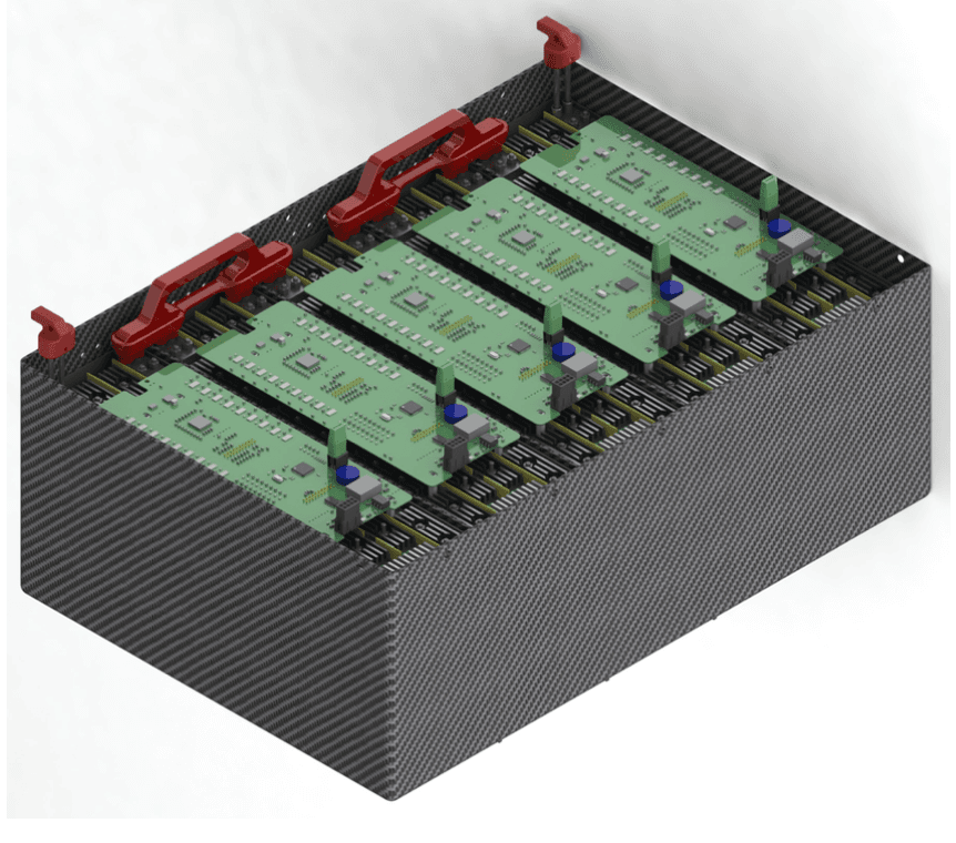
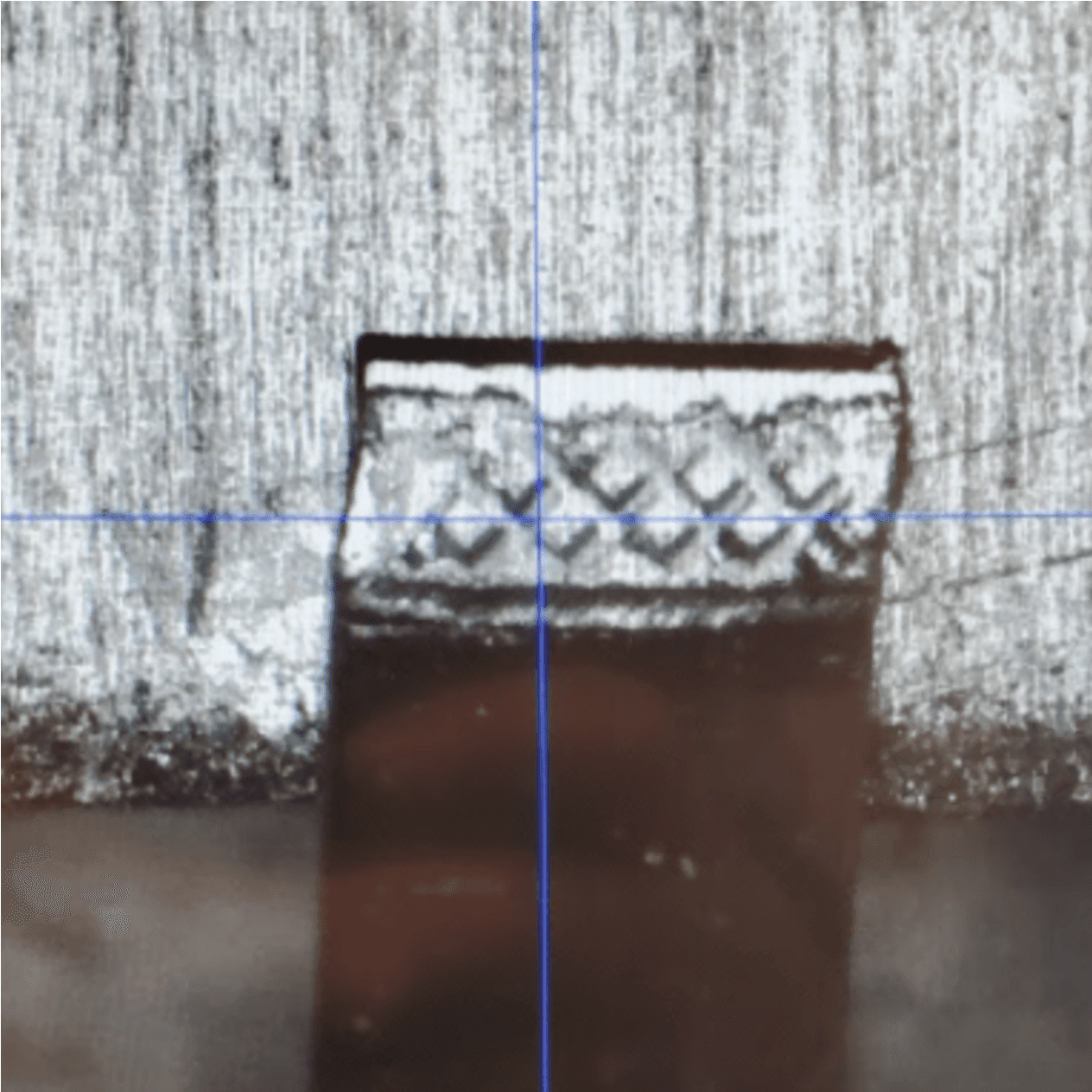
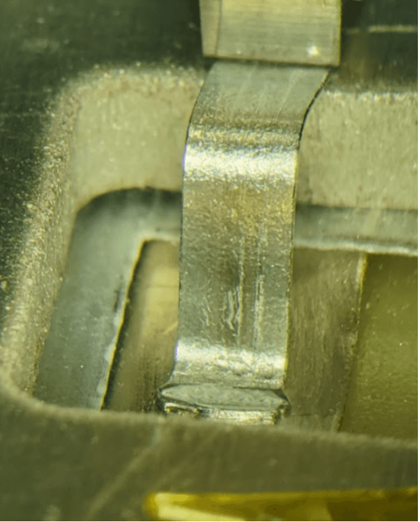
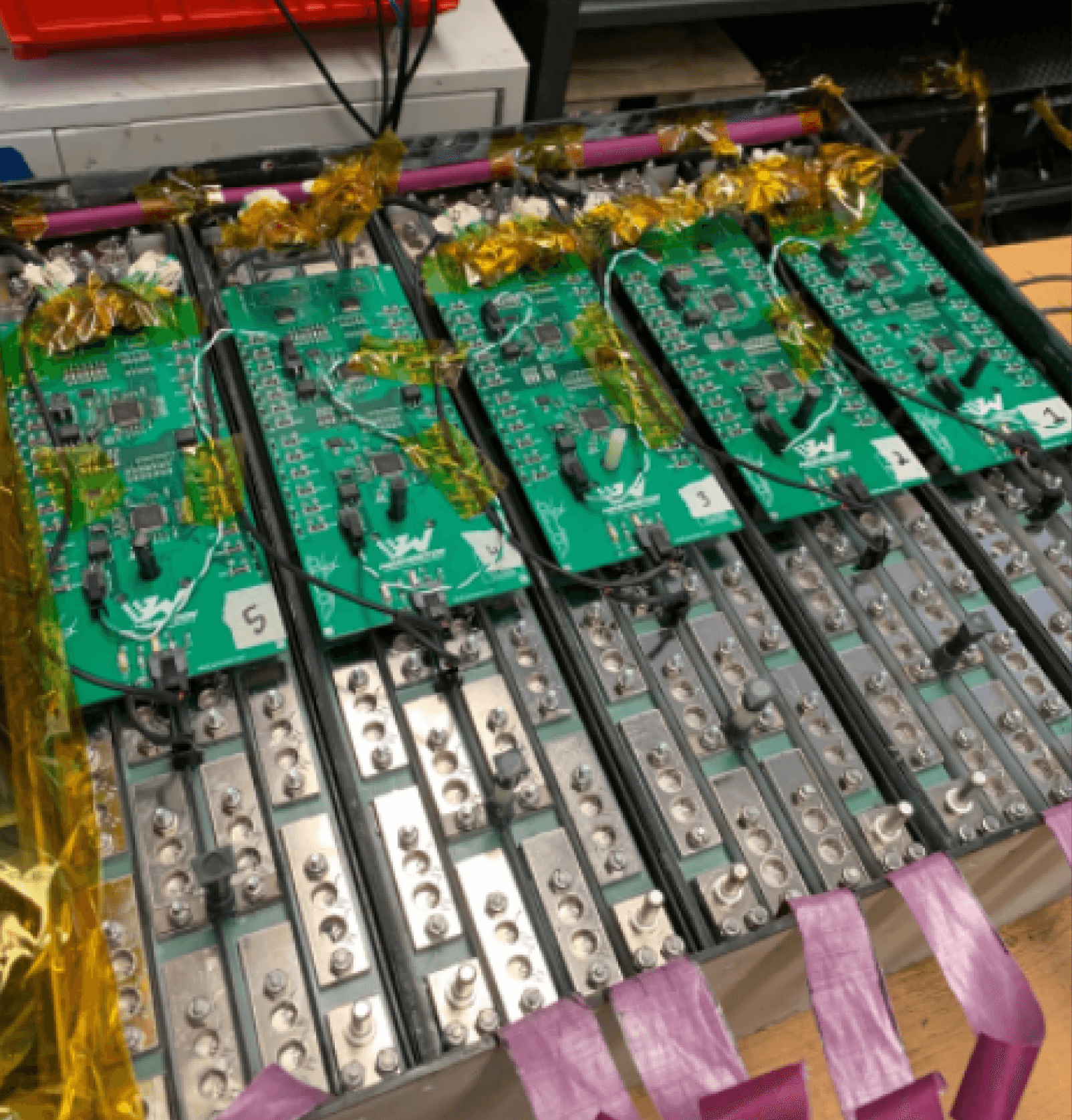
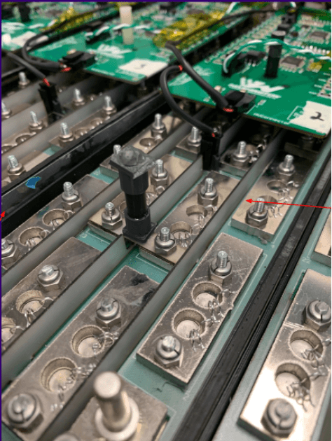
The flexible terminals of LiPo cells make spot welding challenging, risky and plain sloppy. Through the R&D process I connected with Mike, an engineer at Hesse, who offered a new approach to fuse our pack using ultrasonic ribbon bonding—ensuring quality without compromising safety.
Fuses pictured in dark green above
+
-
+
-
+
-
+
-
These modules are then connected to each other in series to form our high voltage battery
+
-
+
-
+
-
+
-
+
-
600V Battery Pack
Repeatedly connecting virtual cells in series creates modules
120V Module
75V Module
+
-
+
-
Those “virtual cells” are then repeatedly connected in series to each other with busbars
+
-
+
-
+
-
+
-
3 virtual cells in series = 12.6V
Increases voltage 1.5X
+
-
+
-
+
-
2 virtual cells in series = 8.4V
A combination of cells connected in parallel called a virtual cell.
+
-
+
-
Newly Designed Virtual Cell is 2P
Previous Design Virtual Cell is 3P
+
-
+
-
+
-
This is a 4.2V lithium ion battery cell
+
-
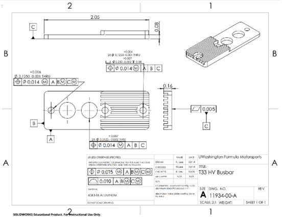
This is a busbar, a metal conductor used to connects cells
Conceptual Design
Build a high voltage battery for an FSAE race car with the following characteristics:
600V
Parallel Cell Fuses
Same Size/Weight as Previous 400V Pack
Costs less than $10,000
Capable of finishing FSAE endurance race
In Short
My Engineering Process
I start with my requirements, in FSAE most are derived from the official rulebook and the rest come from internal collaboration across subteams. For instance the motor selected this year drove the increase in pack voltage, however the cell fusing comes from the FSAE rulebook.
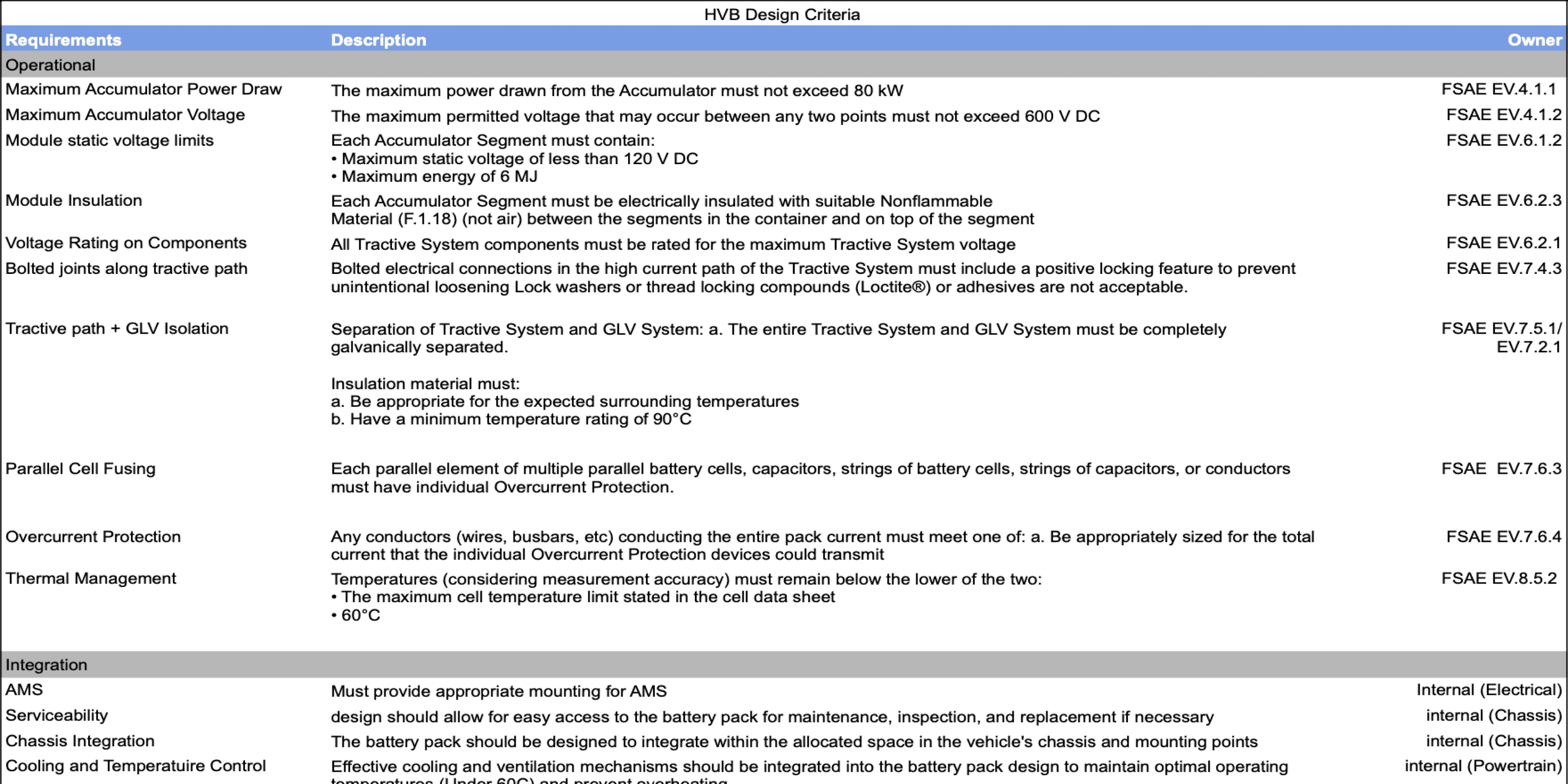
Design Criteria
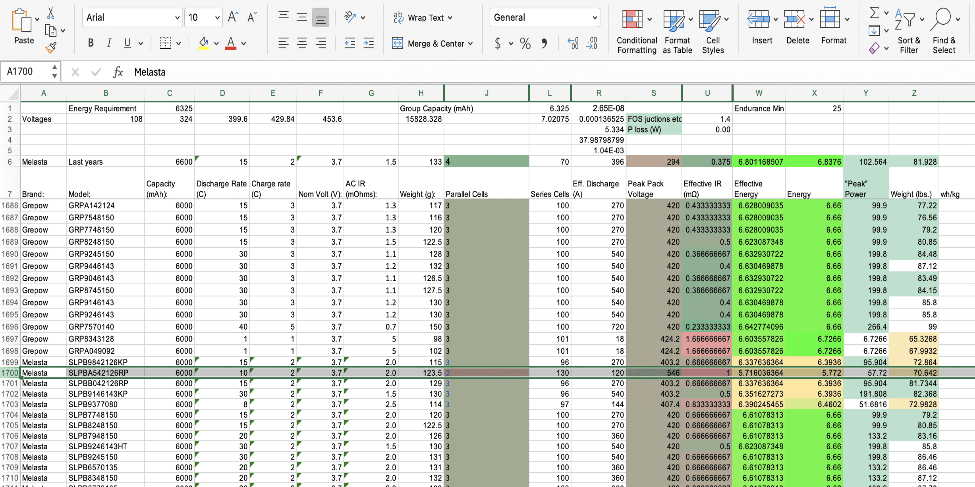
Calculator compares characteristics of 2500 lithium ion battery cells to determine ideal pack architecture
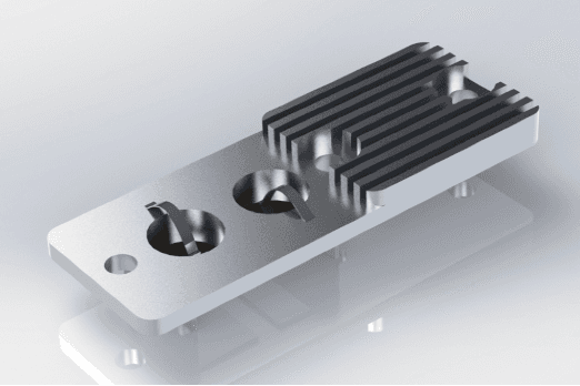
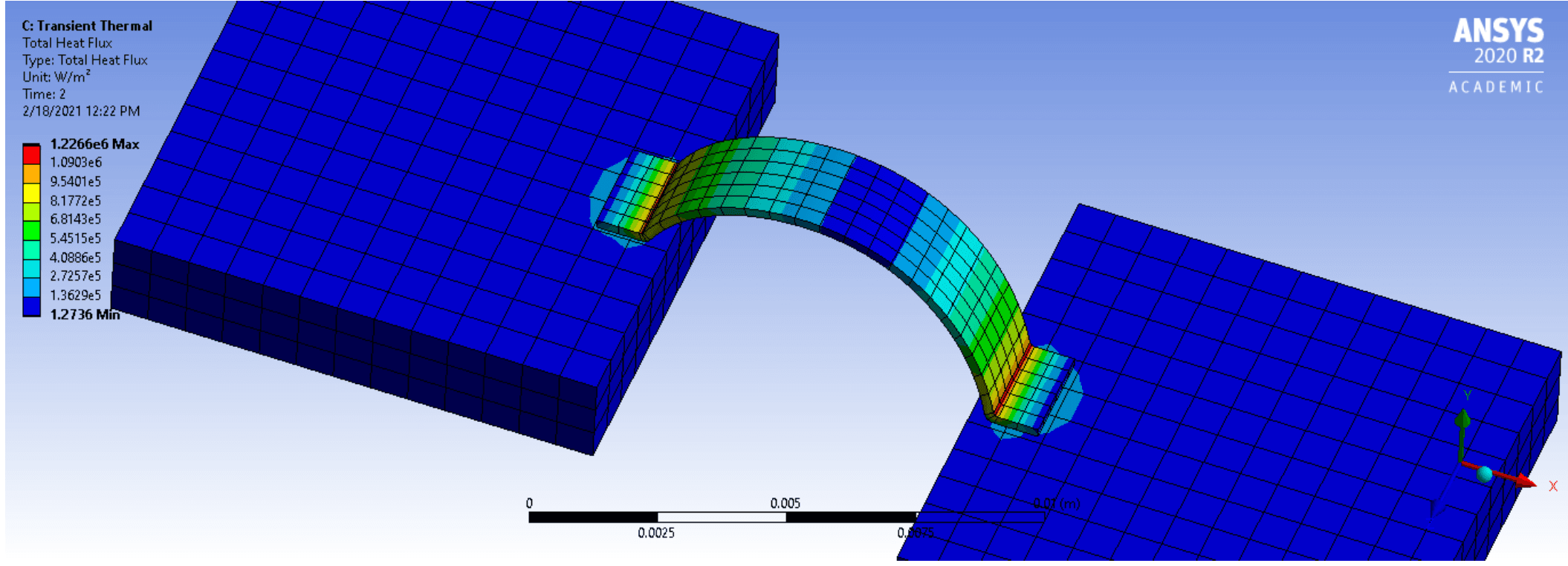
Preliminary module design used to inform general footprint, high voltage path, and busbar sizing
Preliminary Design and Requirements

After running through PDR the next step is to finalize the design in CAD with detailed design, manufacturing drawings, integration with the full vehicle assembly and and simulation work.
Detailed Design and Analysis
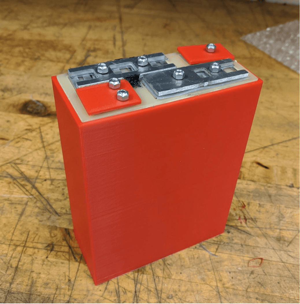
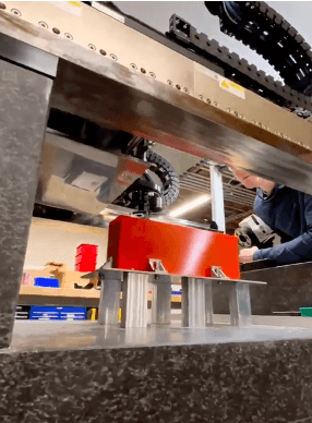
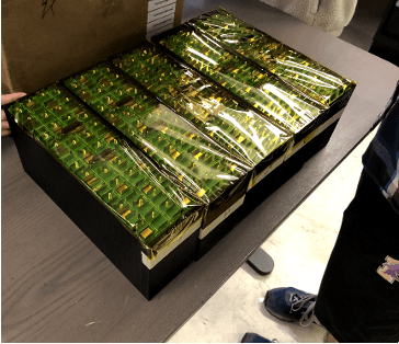
I ran an extensive testing campaign using a DC load to ensure that our fusing solution would adequately protect our driver. Additionally I prototyped a sample module that was shipped to our sponsor to verify the feasibility of the fusing manufacturing process.
Testing
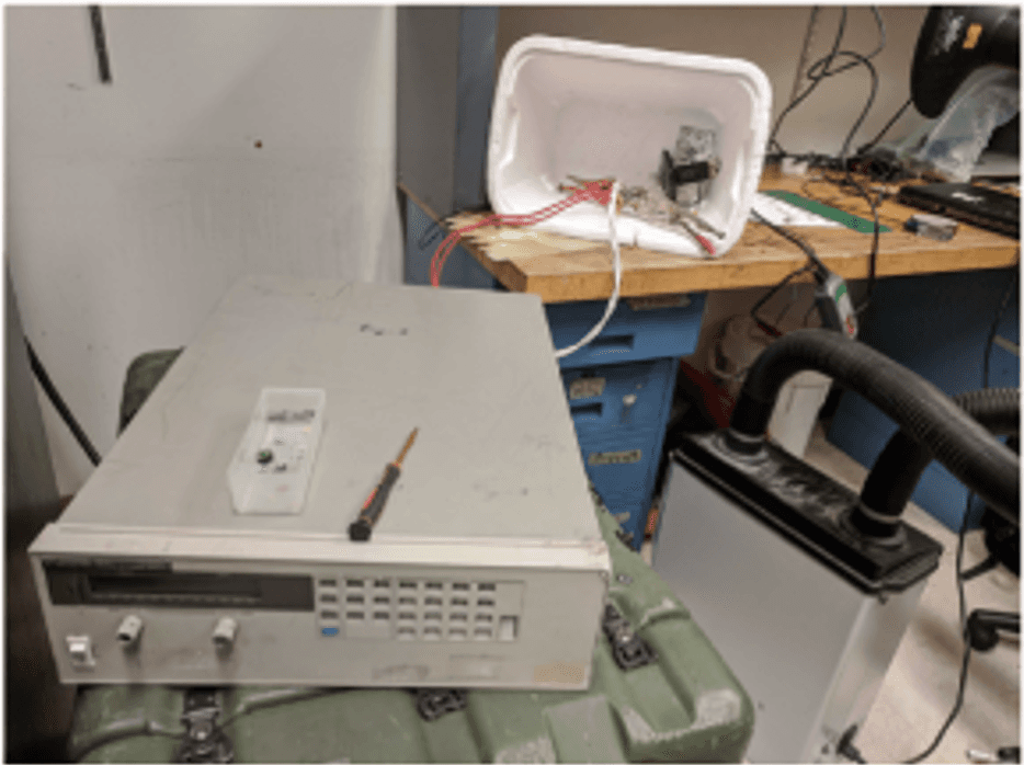
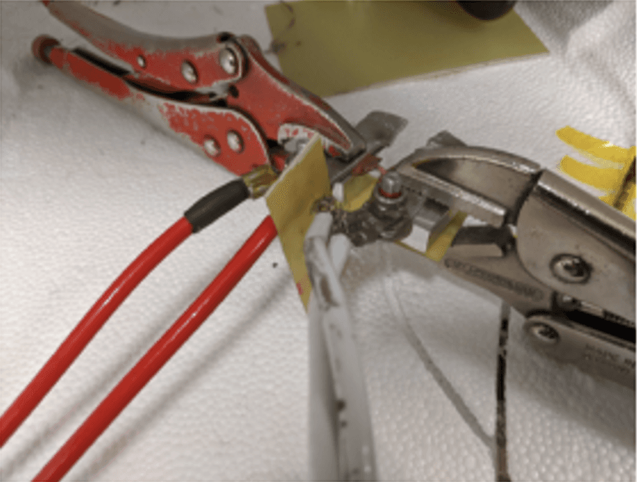
Fusing time testing using power supply
Sample module shipped to sponsor Hesse to confirm fusing process
With the cell stack having successfully passed a series of design reviews and a rigorous pre-build testing campaign, it was time to begin manufacturing and integration. This phase involved machining 130 busbars, transporting the assembly to our sponsor's facility for fusing, and carefully handling high-voltage systems as they were integrated into the rest of the vehicle.
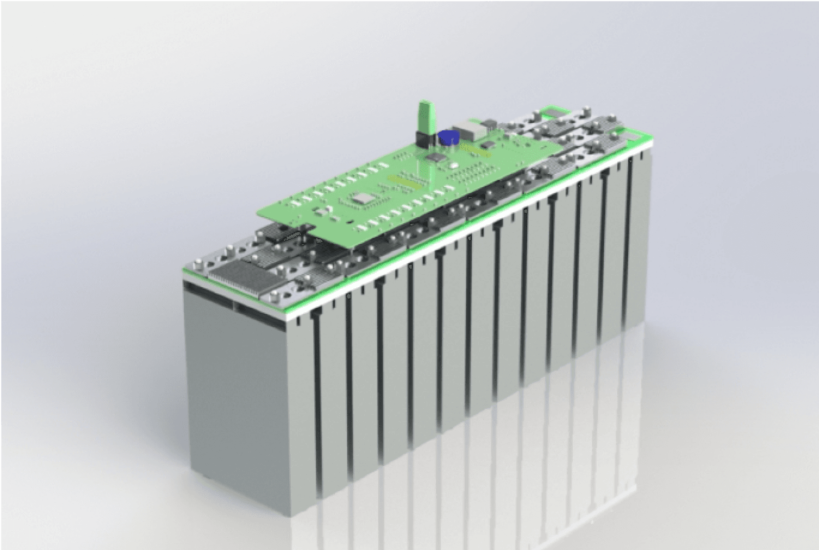
Manufacturing and Integration


Full Assembly and Integration of the Cell Stack! Car is ready to vroom!!