45°
Resultant Strength Vector shows Quasi Isotropic Material Strength
Plys are stacked providing fiber strength in all directions at 45° increments
0/90 Ply
45/45 Ply
The concept for making this project work is to take an anisotropic material like carbon fiber, and make it quasi-isotropic by laying plys in different directions on top of each other what this does is creates tensile strength in 0/90 and 45/45 degree directions
Conceptual Design
When I took on this project, the FSAE judging committee had just greenlit composite battery structures, making ours one of the first attempts in competition history. Being first adopters of FSAE rule changes often presents huge performance opportunities but also its own brand of chaos. In this case, it meant completely redesigning this safety-critical powertrain assembly from the ground up, incorporating rigorous composite material equivalency testing, design for manufacturability (DFM) considerations, and executing a complicated and completely new layup process for our team.
A first of it’s kind design and a departure from aluminum battery enclosures.
Challenge and Evolving Hardware
Composite Battery Enclosure
Battery Box
Testing was a crucial part of this project, as we needed to demonstrate structural equivalency to an aluminum enclosure. To achieve this, I conducted a three-point bend test, perimeter shear test, and bracket adhesive lap joint test. Also included was the first trial runs with laying up the composite selected for this project to make the test panels.
After completing the required testing, we received Structural Equivalency Submission (SES) approval from the design judges, officially clearing us to begin manufacturing.
Testing
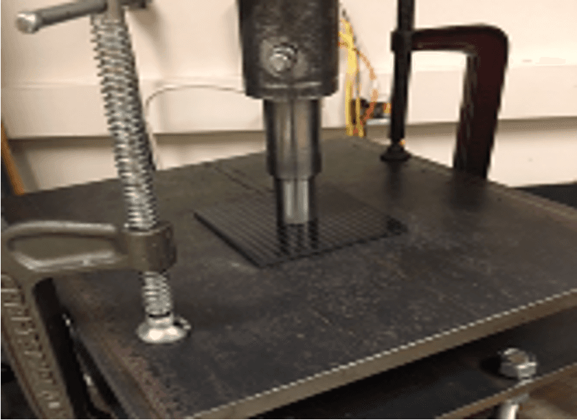
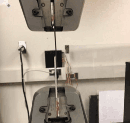
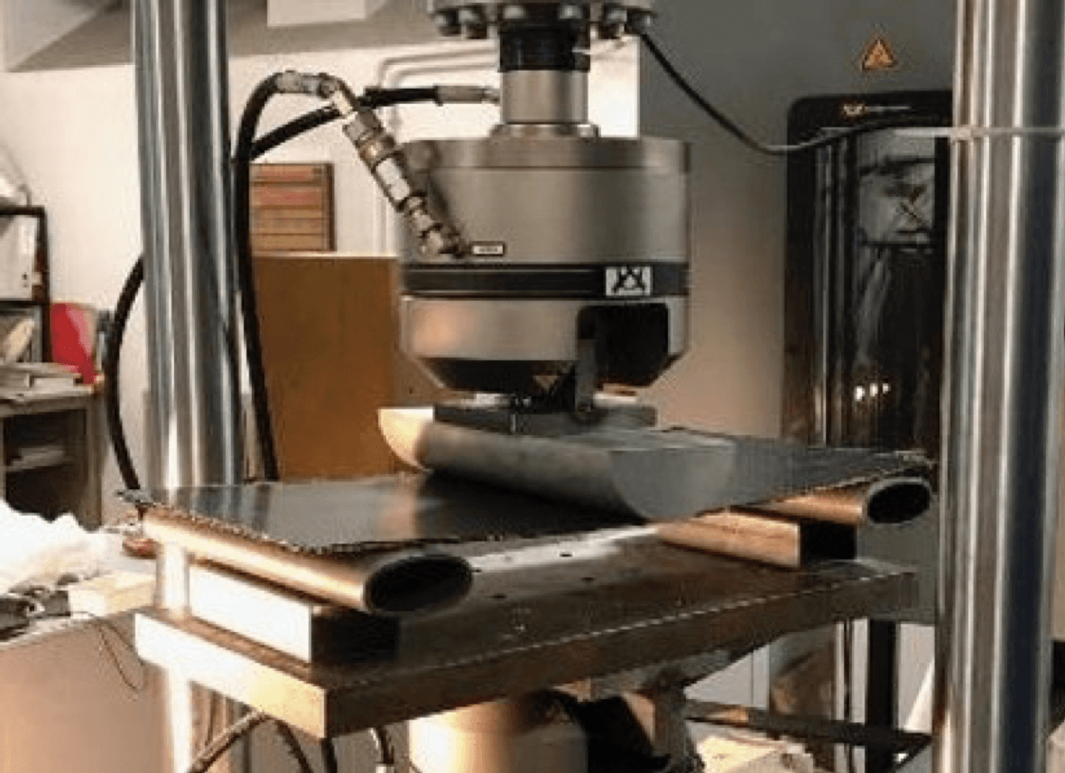
3 Point Bend, Lap Shear, and Perimeter Shear Testing
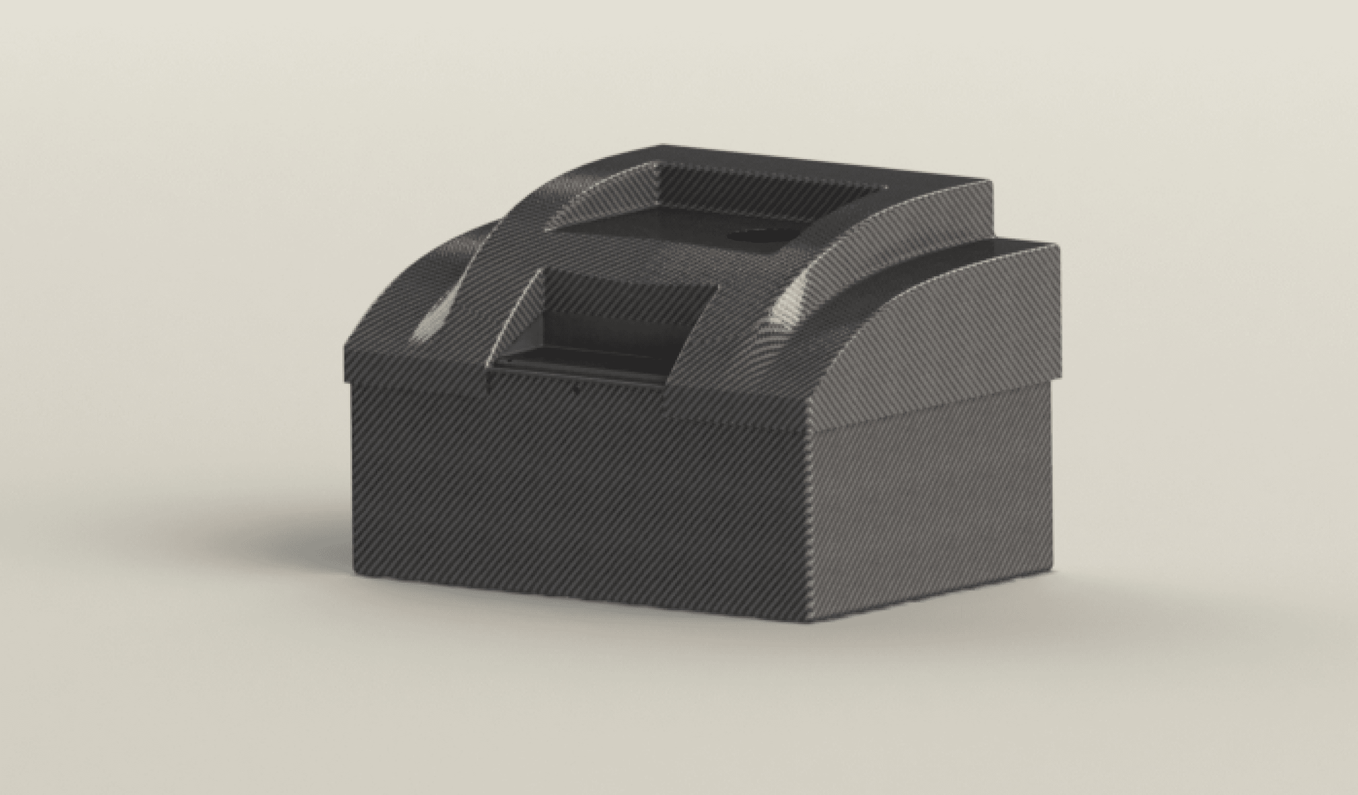
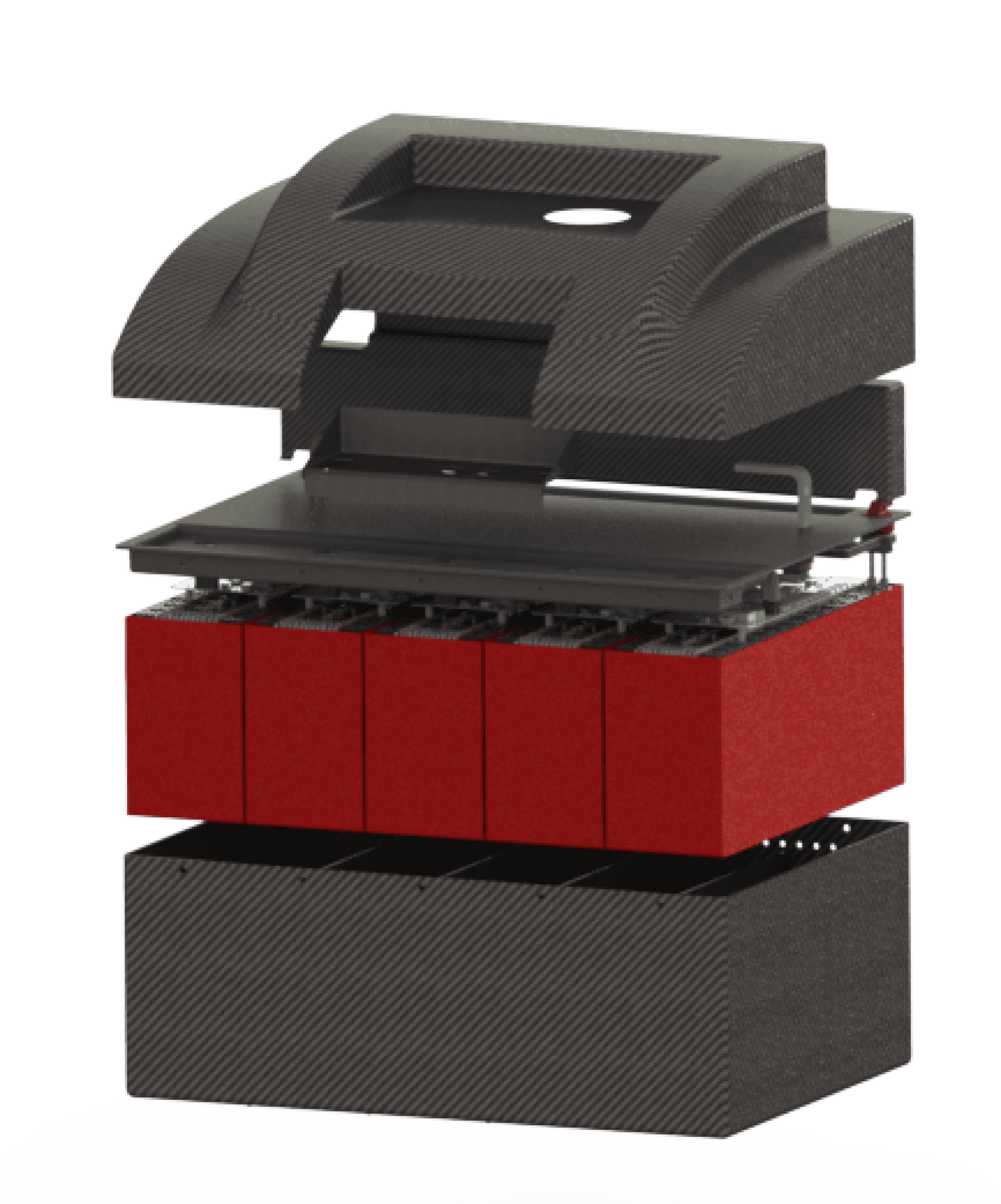
The final design shown below proved to be 45% lighter than previous aluminum enclosures and successfully houses not just the vehicle’s high voltage battery but also the low voltage systems housed in the subsystem’s upper tray. Similar to the cell stack project this design is guided by the regulations set by the FSAE rulebook as well as internal requirements set by the chassis and powertrain team.
Engineering Design
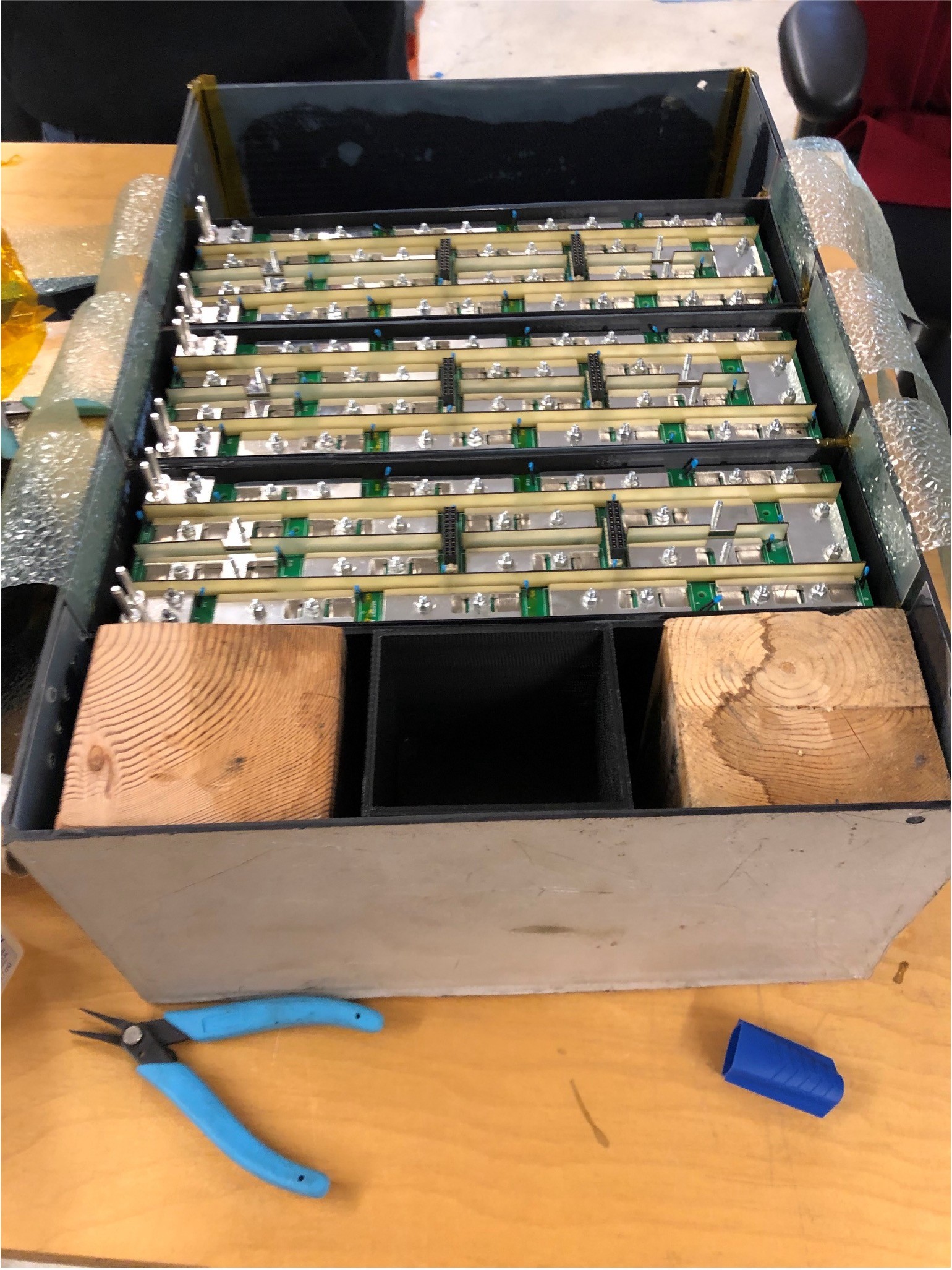
Manufacturing this project proved to be the most challenging phase by far. It involved designing, fabricating, and preparing the mold, followed by an intense layup process that took Alex and me nearly 20 continuous hours to complete. After curing, we focused on post-processing the enclosure and adhering the brackets and module dividers. This was by far the hardest/most humbling part of this project and gave me a deep sense of appreciation for manufacturing hardware.
Manufacturing
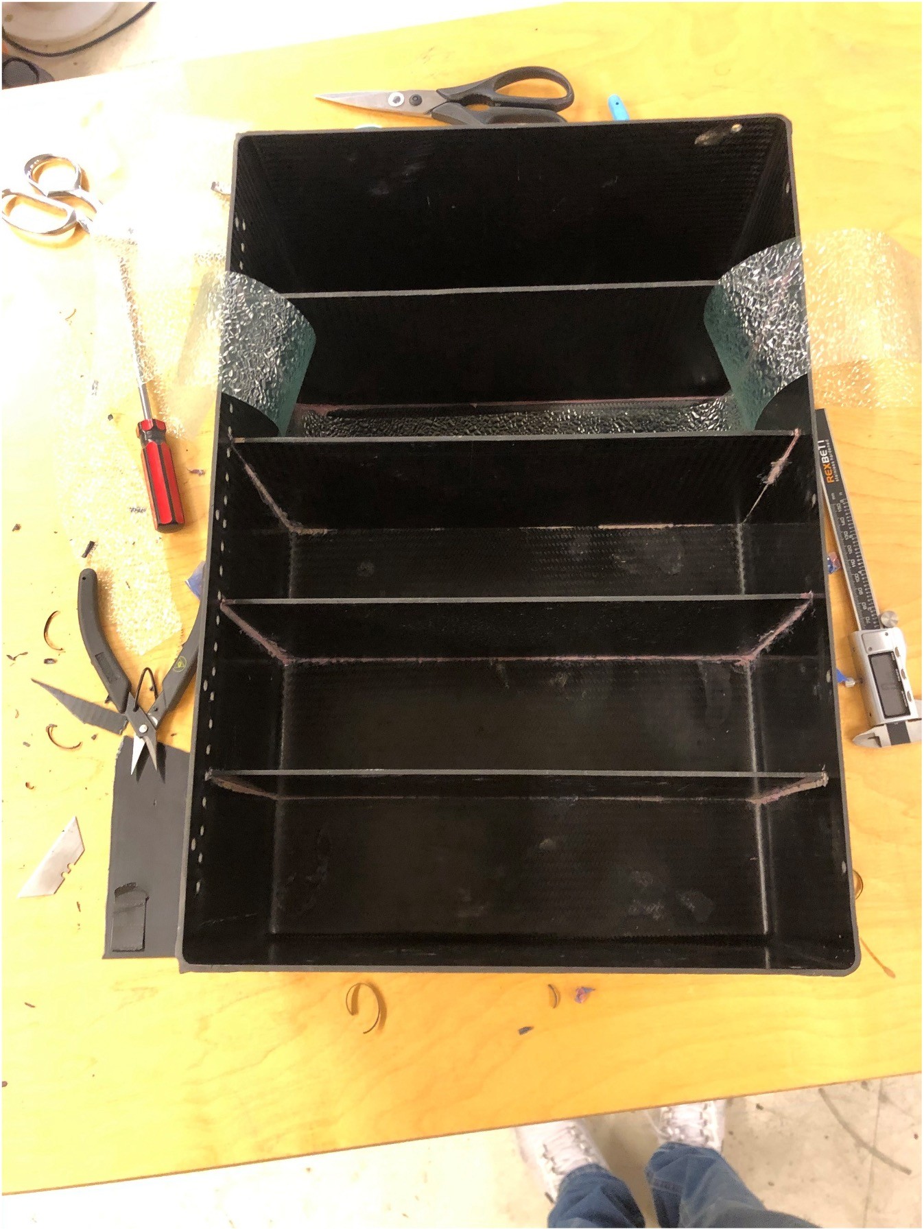
Adhering module dividers using assembly jigs
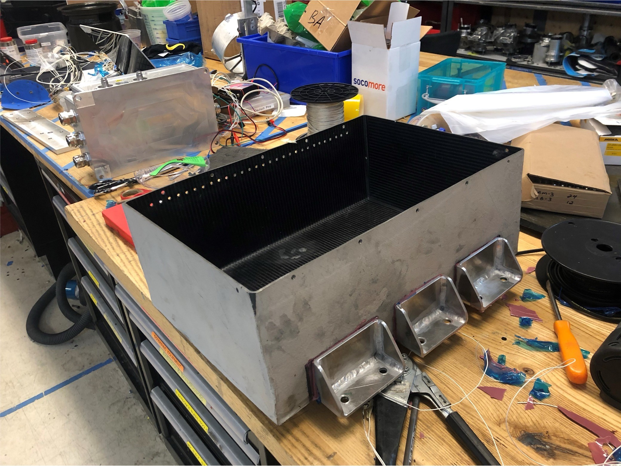
Chassis mounting brackets adhered to sidewalls of enclosure
Dividers finished curing
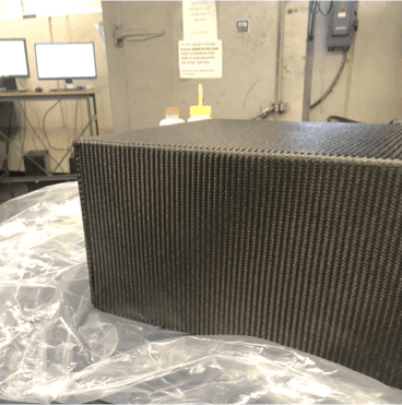
Laying up CF onto Mold
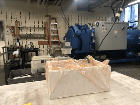
Vacuum Bagging
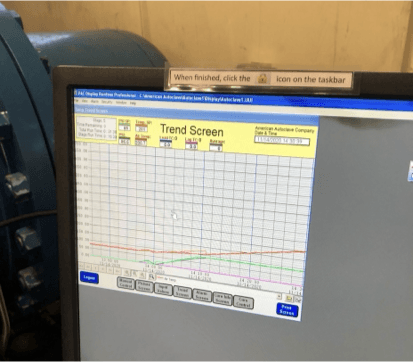
Run autoclave to cure resin
Completed Battery Box :)
When all was said and done, this project demanded countless hours on the less glamorous side of engineering—and every possible mistake was made along the way. However, overcoming those challenges that come with designing something entirely new made the final product all the more rewarding. What’s not visible in this presentation is the endless supply of sandpaper used, along with plenty of sweat and tears—these were the true testaments to the effort poured into every detail to bring this project to life.
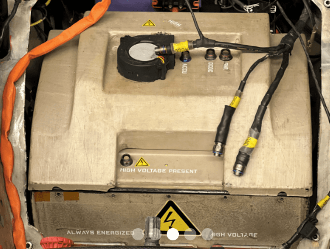
Finished Enclosure Integrated in Vehicle at FSAE